AQUATIC ECOSYSTEM MONITORING REMOTE VEHICLE.
 IJAR Indexing
visibility
…
description
10 pages
link
1 file
Sign up for access to the world's latest research
checkGet notified about relevant papers
checkSave papers to use in your research
checkJoin the discussion with peers
checkTrack your impact
Abstract
This paper reports the Underwater Vehicles for Surveillance and Monitoring Aquatic Ecosystem. The acceptable range of pH for aqua environment is between pH 6.0 to pH 8.0. Different problems associated with aquatic ecosystem due to water pollution are increasing pH and temperature due to global warming and decrease of dissolved oxygen. This is endangering the various aquatic species. Besides this, water becomes unusable for drinking, farming and for general work. So a microcontroller based un-manned vehicle for monitoring the water purity parameters viz.; pH and temperature using wireless communication is presented here. It has a aqua monitoring unit which continuously monitors the purity of water and sends an alarm to the central monitoring unit in case the water turns abnormal acidic/alkaline and gives an information on speed of wind, floating debris, possibility on earth quake through earthquake signals sensed in water etc. This helps for ensuring the safety of aquaculture as well as human being.
Figures (12)


Related papers
Unmanned Underwater Vehicle for Monitoring Aquatic Ecosystem
International Journal of Engineering Applied Sciences and Technology, 2020
Collection of Data by Survey and Observation in the actual aquatic environment is indispensable for studies and development. Studies about ocean such as Marine Environment Monitoring, submarine Earthquakes, Ocean life, marine Resource Research are carried out with the help of an underwater vehicle. While the existing underwater vehicles provide a high cost, less effective, inaccurate data processing solution, the problem is addressed by choosing a highly efficient microcontroller PIC18 Microcontroller with its excellent capability for image processing, video streaming and the ability to work based on internet of things. In this paper a low cost and an efficient underwater vehicle is designed and implemented which has the ability to measure parameters like temperature and pressure using sensors.
Real-Time Water Quality Monitoring For Small Aquatic Area Using Unmanned Surface Vehicle
Engineering, Technology & Applied Science Research, 2019
Most developing countries depend on conventional water quality monitoring methods which are usually expensive, complicated, and time-consuming. In recent years, stationary and portable water quality monitoring and a mobile surface vehicle have increased the utilization of on-site water measurements and monitoring. The first has the disadvantage of small coverage area while the second has its cost and operational complexity. This paper addresses these issues by placing materials and equipment used in fixed online water quality monitoring and using a customized and low-cost unmanned surface vehicle. The measurements are taken automatically on the equipment onboard the unmanned surface vehicle (USV), transmitted wirelessly to a PC-based remote station or nearby stations and saved there in a dedicated database. The overall system comprises a commercial water quality sensor, a GSM and Zigbee module for a wireless communication system, a low-cost mobility platform, and the location/positi...
IETE Journal of Research Design of a Low-cost Underwater Wireless Sensor Network for Water Quality Monitoring Design of a Low‑cost Underwater Wireless Sensor Network for Water Quality Monitoring
With the ongoing advancements in the field of wireless technologies and sensor networking, a lot of research is taking place in using such sensor networks for multitude monitoring situations, e.g. home, office monitoring systems, body area sensor networks, and environmental monitoring systems. These systems cost a lot and are complicated as in operating. Thus, our main goal is the development of low‑cost, yet effective sensor networks for monitoring the quality of water bodies like lakes, water reservoirs, ponds, etc., Such systems would be deployed in a lake, a small reservoir, etc., which would relay back the real‑time values of different parameters like pH, turbidity, temperature, etc., to the monitoring station wirelessly in an efficient and cost‑effective manner.
A system for monitoring water quality in a large aquatic area using wireless sensor network technology
Sustainable Environment Research
In this paper, a low cost, real-time water quality monitoring system which can be applied in remote rivers, lakes, coastal areas and other water bodies is presented. The main hardware of the system consists of off-the-shelf electrochemical sensors, a microcontroller, a wireless communication system and the customized buoy. It detects water temperature, dissolved oxygen and pH in a pre-programmed time interval. The developed prototype disseminates the gathered information in graphical and tabular formats through a customized web-based portal and preregistered mobile phones to better serve relevant end-users. To check the system effectivity, the buoy's stability in harsh environmental conditions, system energy consumption, data transmission efficiency and webbased display of information were carefully evaluated. The experimental results prove that the system has great prospect and can be practically used for environmental monitoring by providing stakeholders with relevant and timely information for sound decision making.
Use of Wireless Sensor and Microcontroller to Develop Water-level Monitoring System
Indian Journal of Science and Technology
This paper presents the design and development process of Wireless Data Acquisition System (WiDAS) which is a multisensor system for water level monitoring. It also consists of a microcontroller (ATMega8L), a data display device and an ultrasonic distance sensor (Parallax Ping). This wireless based acquisition system can communicate through RF module (Tx-Rx) from the measurement sources, such as sensors and devices as digital or analog values over a period of time. The developed system has the option to store the data in the computer memory. It was tested in real time and showed continuous and correct data. The developed system is consisting of a number of features, such as low energy consumption, easy to operate and well-built invulnerability, which cangive successful results to measure the water level. Finally, its flexibility facilitates an extensive application span for self-directed data collection with trustworthy transmission in few sparse points over huge areas.
Design of a low-cost underwater wireless sensor network for water quality monitoring
IETE Journal of Research, 2013
ABSTRACT With the ongoing advancements in the field of wireless technologies and sensor networking, a lot of research is taking place in using such sensor networks for multitude monitoring situations for example, Home, office monitoring systems, Body Area sensor networks, and Environmental Monitoring systems. These systems cost a lot and happen to be complicated as in operating, thus our main goal being the development of low cost yet effective Sensor Networks for monitoring the quality of water bodies like lakes, water reservoirs, ponds etc. such systems would be deployed in the field like a lake or a small reservoir etc., which would relay back the real time values of different parameters like the pH, turbidity, temperature etc. to the monitoring station wirelessly in an efficient, cost effective manner.
Design of Low-cost Autonomous Water Quality Monitoring System
—Good water quality is essential for the health of our aquatic ecosystems. Continuous water quality monitoring is an important tool for catchment management authorities, providing real-time data for environmental protection and tracking pollution sources; however, continuous water quality monitoring at high temporal and spatial resolution remains prohibitively expensive. An affordable wireless aquatic monitoring system will enable cost-effective water quality data collection, assisting catchment managers to maintain the health of aquatic ecosystems. In this paper, a low-cost wireless water physio-chemistry sensing system is presented. The results indicate that with appropriate calibration, a reliable monitoring system can be established. This will allow catchment managers to continuously monitoring the quality of the water at higher spatial resolution than has previously been feasible, and to maintain this surveillance over an extended period of time. In addition, it helps to understand the behavior of aquatic animals relative to water pollution using data analysis.
To Assess the Level of Knowledge Regarding Selected Minor Ailments of Pregnancy and Its Remedial Measures Among Antenatal Women Attending Antenatal Opd at Doon Medical College and Hospital, Dehradun
Zenodo (CERN European Organization for Nuclear Research), 2022
Statement of the problem:-A study to assess the level of knowledge regarding selected minor ailments of pregnancy and its remedial measures among antenatal women attending antenatal OPD at Doon medical college and hospital, Dehradun .
Life history patterns of parental and hybrid Daphnia differ between lakes
Freshwater Biology, 2004
1. We investigated whether Daphnia galeata • hyalina hybrids of Lake Constance and Lake Greifensee show the same pattern of life history parameters as previously reported for D. galeata • cucullata hybrids and whether such a pattern is consistent between Daphnia populations from those two lakes. 2. Hybrids in Lake Constance were intermediate in size compared with the parental species. Hybrids in Lake Greifensee were smaller than D. galeata. The intrinsic growth rate (r) of hybrids from Lake Constance was not significantly different from the faster growing parental taxon D. galeata. However, r of hybrids from Lake Greifensee was significantly lower than that of D. galeata. 3. The observed juvenile body length differences between the taxa varied with the clutch number. The first clutch juvenile lengths of the three taxa did not differ for Lake Constance. First clutch juveniles of Lake Greifensee D. galeata were smaller than hybrid first clutch juveniles. The third clutch juvenile length did not differ between taxa from Lake Greifensee, but D. galeata juveniles from Lake Constance were bigger than those of D. hyalina. 4. The life history pattern found in Lake Constance corresponds to previous findings from other studies. The hybrids in this lake combine the faster population growth of one parental species with a relatively small size. In the case of Lake Greifensee hybrids, the relatively large size of first clutch juveniles and the small size of the adults could be interpreted as dual adaptations to invertebrate and fish predation. We speculate that the lower population growth rate of the hybrids is a trade-off for this twofold protection.
ISSN: 2320-5407
Int. J. Adv. Res. 6(5), 1086-1095
Journal Homepage: -
www.journalijar.com
Article DOI:
Article DOI: 10.21474/IJAR01/7132
DOI URL: http://dx.doi.org/10.21474/IJAR01/7132
RESEARCH ARTICLE
AQUATIC ECOSYSTEM MONITORING REMOTE VEHICLE.
1.
2.
Dabholkar Aakshay V1, Takade hiraj D1, Todkar Premraj S1 and Dr. V. Jayashree2.
Undergraduate Students at DKTE Society’s Textile & Engineering Institute, Ichalkaranji.
Professor Electronics at DKTE Society’s Textile & Engineering Institute, Ichalkaranji.
……………………………………………………………………………………………………....
Manuscript Info
Abstract
…………………….
………………………………………………………………
Manuscript History
Received: 18 March 2018
Final Accepted: 20 April 2018
Published: May 2018
Key words:AEMV, pH, aqua culture, ATMega328,
Central Monitoring Unit, Aqua
Monitoring Unit.
This paper reports the Underwater Vehicles for Surveillance and
Monitoring Aquatic Ecosystem. The acceptable range of pH for aqua
environment is between pH 6.0 to pH 8.0. Different problems
associated with aquatic ecosystem due to water pollution are
increasing pH and temperature due to global warming and decrease of
dissolved oxygen. This is endangering the various aquatic species.
Besides this, water becomes unusable for drinking, farming and for
general work. So a microcontroller based un-manned vehicle for
monitoring the water purity parameters viz.; pH and temperature using
wireless communication is presented here. It has a aqua monitoring
unit which continuously monitors the purity of water and sends an
alarm to the central monitoring unit in case the water turns abnormal
acidic/alkaline and gives an information on speed of wind, floating
debris, possibility on earth quake through earthquake signals sensed in
water etc. This helps for ensuring the safety of aquaculture as well as
human being.
Copy Right, IJAR, 2017, All rights reserved
……………………………………………………………………………………………………....
Introduction:-
The ocean occupies approximately 71% of the earth surface and still has a lot of unexplored parts. Therefore,
various studies and development about the ocean such as marine environment, earthquake, ocean life, and marine
resources research and so on are carried out. Plenty of survey data and observation of the actual sea is available for
the studies and the development. Remotely operated vehicle can play an important role in monitoring, protecting and
maintaining the aquatic ecosystem which is polluted by waste chemicals from factories, oil spilling in oceans,
accidents caused due to ships etc. Hence there is a need of a low cost, highly efficient underwater vehicle which can
serve multiple applications. Indian aquaculture is facing a number of problems today. Indian shrimp production went
low to 2% of total world shrimp production and contributed to an export of 1730 million dollars in 2009. There are
several reasons for such a low production. The acceptable range of pH for aqua environment is in the range of pH
6.0 to pH 8.0. When pH of water is above 9, then it is very alkaline, then ammonium in water is converted to toxic
ammonia, which is dangerous to survival of shrimps. On the other hand, pH of water below 5 makes it acidic water
which leeches metals from rocks and sediments. The correct pH, alkalinity and hardness are essential for a
successful aqua life where fertilizers containing nitrogen, phosphorous and potassium are added to encourage the
growth of aqua culture.
Anuradha A. Maindalkar, Saniya M. Ansari designed an instrumentation for underwater vehicle using a wireless
module, and software for real-time in-field sensing and control of a site-specific precision system. The conceptual
Corresponding Author:- V. Jayashree.
Address:-DKTE Society’s Textile & Engineering Institute, Ichalkaranji.
1086
ISSN: 2320-5407
Int. J. Adv. Res. 6(5), 1086-1095
layout is useful for the transmission and reception of information through wireless module [1]. A low Cost Remote
Controlled Underwater Rover is useful for studying the underwater life and all the underwater activities to learn
about the underwater life[2]. In paper by G. Divya Priya and Mr.I. Harish describes an application of a wireless
module and Raspberry Pi for low-cost wireless controlled underwater vehicle that removes the need for
workmanship for monitoring water resources for its pollution. The Arduino an Embedded Computing platform, uses
the hardware and software that can interact with it’s environment [3]. Koushik Reddy, et al. have reported the
details about Dissolved Oxygen sensor, PH sensor, Ultra Sonic Sensor etc. which are connected to a base device
called Arduino Board. The device automated using the internet. The conceptual layout is useful for the design of
aquatic ecosystem monitoring vehicle [4]. Underwater Remotely Operated Vehicle (ROV) for a shallow water
environment (up to 10m depth) was developed using Fuzzy Logic motion control and electronic power control. The
main controlling unit of the electronics is a Raspberry pi microcomputer operates the video. Very satisfactory
operation were observed for test trials of the ROV conducted in a laboratory water tank to a depth of about 1.5 m[5].
An autonomous underwater vehicle (AUV) an interdisciplinary coastal research was deployed to collect chlorophyll
fluorescence, optical backscattering (880nm), and physical data. It sampled the region to quantify various features in
both physical and bio-optical properties in the Bays[6].
Based on the literature survey, we aim to develop & implement aquatic ecosystem monitoring system for aqua
culture of shrimps by monitoring the water purity parameters such as pH, and temperature of water using wireless
communication for ensuring the safety for aquaculture as well as human being.
Methodology:A. Block Diagram of Aquatic System
Figure 1 shows the block diagram of our project. This figure gives the requirement of the system i.e. microcontroller
block, LCD, sensors, battery bank and mechanical arrangement.
The block diagram of our project consists of mainly two parts, viz., Part-1 consists of central monitoring unit and
Part-II Atmega based aqua monitoring unit is as shown in Figure 1. Different subblocks of the system are as follows,
a) Arduino with ATmega 328. 2)Temperature sensor, 3)pH sensor, 4)Wind speed sensor, 5)Vibration sensor,
6)Ultrasonic sensor, 7)LCD display, 8)Zigbee Module, 9)DC motor and mechanical assembly , 10)Battery bank.
1) ATmega 328 microcontroller:
The purpose behind the selection of ATmega 328 microcontroller is that it is very simple to use and very powerful
device. It has in built ADC section, 8 and 16 bit timer section, watch dog timer, Low voltage programming and
PWM control.[7].
2) Temperature sensor: Temperature sensor DS18B20 is used to detect temperature of water resource. It is a
smart digital temperature sensor which gives 12 bit digital output with resolution of 0.069v/0C. It works at low
voltage and gives precise temperature values.
1087
ISSN: 2320-5407
Int. J. Adv. Res. 6(5), 1086-1095
Central monitoring Unit
Unit
Personal
Zigbee
Wireless communication
Water
Pollution
Departm
Computer
(Database)
Aqua
monitoring
Unit
Piezo
Sensor
Wind
Sensor
Battery
Bank
Temperature
Sensor
ATmega 328
(UVSMA&E )
pH sensor
Motor
Driver
Left
Motor
Right
Motor
LCD
Display
Zigbee Module
(Rx/T
Aquatic
Robot
Figure (1):- Block diagram of implemented system
3) pH sensor: pH sensor is used indicate the acidity/alkalinity of a water resource. CSL 31 is an analog sensor
with glass body, refillable, ceramic diaphragm pH electrode with low noise co-axial cable.
4) Wind speed sensor: Wind speed sensor used in this project is a 5V DC voltage which generates dc voltage
in accordance with wind speed. By using a standard formula we can calculate the speed of air.
5) Vibration sensor: Vibration sensor based on Piezo-electric principle is used to detect the turbulence of water
resource. It produces voltage proportional to the vibration present around the aquatic vehicle.
6) Ultrasonic sensor: Ultrasonic sensor is used to detect the obstacles coming in front of AEMV which
produces a trigger pulse and echo pulse to detect the obstacle. If the obstacle is too close to AEMV, then
AEMV gets automatically reversed.
7) LCD display: LCD is used to display the measured values of temperature and pH of water with the help of
16X2 LC.
8) Zigbee Module: Aquatic signals monitored by AEMV are sent to central unit to using wireless control.
Hence, Zigbee module CC2500 is used as the wireless transmission and reception of data.
9) DC motor and mechanical assembly: DC motors operating at 12 volts are used for the movements of
AEMV such as forward, backward and left, right movements. Also we require geared DC motors along with
appropriate DC driver IC i.e. L293D. Also some mechanical arrangement is used for the movements.
A. System Requirement
1)
In this, arduino development board is used to dump the aqua monitor code in the IC ATmega328.
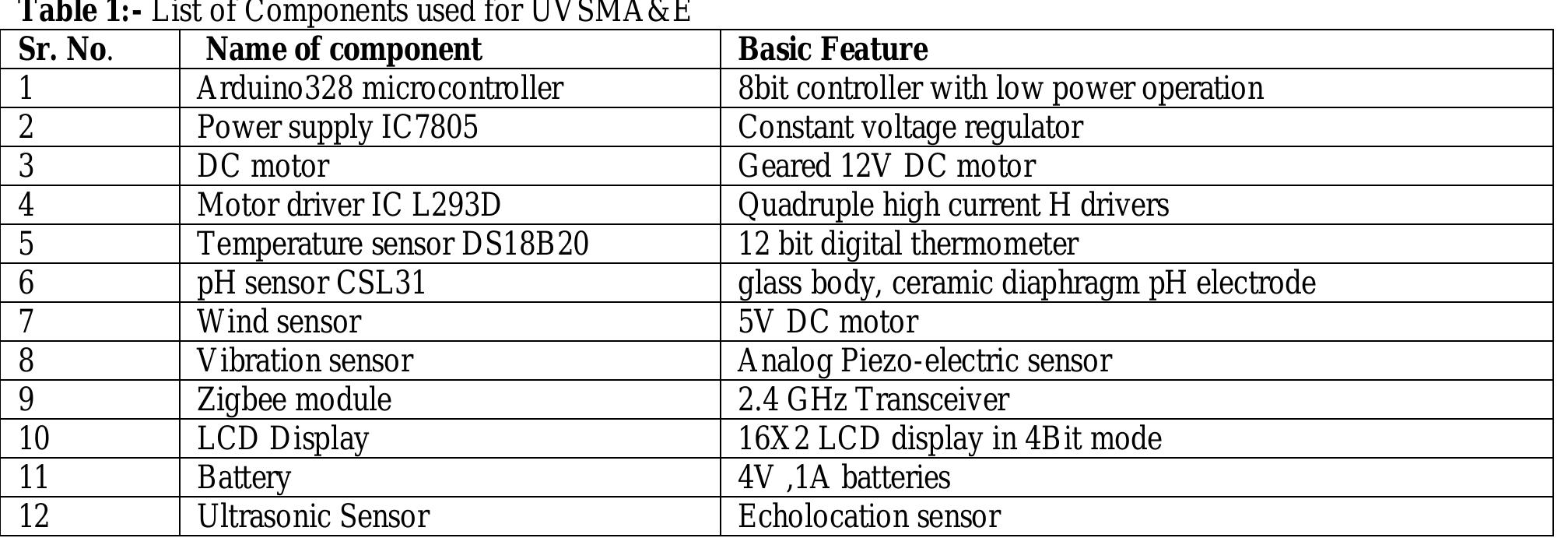
Components used for AEMV are tabulated in Table I.
1088
ISSN: 2320-5407
Int. J. Adv. Res. 6(5), 1086-1095
i. DC motor : DC motor with operating voltage of 12.0VDC output, Speed of 30 +/- 10% RPM, No-Load output
current is less than 50 mA, Rotation Output has noiseless Gear with clockwise and counterclockwise motion.
and No-Load Speed of 5700 RPM & No-Load Current of 30Ma
ii. Motor driver IC L293D: As arduino328 is a low power device, driver IC, The L293D is designed to provide
bidirectional drive currents of up to 600-mA at voltages in the range of 4.5 V to 36 V. All inputs are TTL
compatible. A high enable input enables the associated drivers and make their outputs are active and in phase
with their inputs.
Table 1:- List of Components used for UVSMA&E
Sr. No.
Name of component
1
Arduino328 microcontroller
2
Power supply IC7805
3
DC motor
4
Motor driver IC L293D
5
Temperature sensor DS18B20
6
pH sensor CSL31
7
Wind sensor
8
Vibration sensor
9
Zigbee module
10
LCD Display
11
Battery
12
Ultrasonic Sensor
iii.
iv.
v.
vi.
Basic Feature
8bit controller with low power operation
Constant voltage regulator
Geared 12V DC motor
Quadruple high current H drivers
12 bit digital thermometer
glass body, ceramic diaphragm pH electrode
5V DC motor
Analog Piezo-electric sensor
2.4 GHz Transceiver
16X2 LCD display in 4Bit mode
4V ,1A batteries
Echolocation sensor
Temperature sensor: A water resistant temperature sensor which gives precise temperature readings at low
power supply digital sensor, DS18B20 which is very accurate and operates at 5V supply voltage. The
digital thermometer (DS18B20) has 9-bit to 12-bit Celsius temperature measurements and has an alarm
function with non volatile user programmable upper and lower trigger points. The DS18B20 communicates
over a 1-Wire bus for communication with a central microprocessor. For water resistance feature this
sensor is enclosed in steel bar[10].
Power Supply Range: 3.0V to 5.5V ,Temperatures Range: -55°C to +125°C (-67°F to +257°F) , ±0.5°C
Accuracy from -10°C to +85°C , Thermometer Resolution is User Selectable from 9 to 12 Bits, Converts
Temperature to 12-Bit Digital Word in 750ms (Max)
pH sensor Operating Temperature: 0°C to 100°C Response Time: <10 seconds for 95% response from 7
pH to pH 4.01, has a Glass Membrane Impedance of 200 M, sustain Pressure: Upto 87 psi, and measure pH
range: 0 to 14.00 pH[10].
Wind speed sensor: For the constant flow of water, it is required to have constant air flow surround water
resource. To detect the wind speed, a 5V dc motor with turbines is used. Whenever the air flow appears
across turbines, turbines starts rotating and creating a dc voltage. This voltage value is taken as input and
by using a standard formula in (1) the wind speed in meter/seconds is computed. The formula used to
derive wind speed is as follows.
SensorVoltage=SensorValue*VoltageConversionConstant
windspeed=(sensorVoltage*10)/(2.223694)
Where,
voltageConversionConstant=0.004882814
a
b
Figure(2):- a) Wind Speed Sensor b) Vibration sensor
(1)
(2)
(3)
Figure(3):- Ultrasonic Sensor
1089
ISSN: 2320-5407
Int. J. Adv. Res. 6(5), 1086-1095
vii.
Vibration sensor: As the epicentre of maximum earthquakes are in water resources, so a vibration sensor
has been used to detect sudden change in water turbulence. AEMV will be rerouted and it will sank in
water. A piezo-electric sensor is used to detect the turbulence which is simple and has high sensitivity.
viii.
Ultrasonic distance sensor : Invento INVNT_8 Ultrasonic Module Hc Sr04 is a precise, non-contact
distance measurements from about 2 cm to 3 meters. It requires only two I/O pins of Propeller chip, or
Arduino. This sensor transmits a burst in the form of an output pulse that corresponds to the time
required for the burst echo to return to the sensor. Measurement of the echo pulse width, helps to
compute the distance to target. Specifications are as further.[11]
o Ultrasonic Range is from 2 cm to 3 m, has a burst indicator LED to show sensor activity.
o It has a bidirectional TTL pulse interface on a two I/O pins can communicate with 5 V TTL or
3.3 V CMOS microcontrollers.
o Input trigger is a positive TTL pulse of 2 μs minimum typ
o Echo pulse is a positive TTL pulse, with 10 μs to 18.5 ms.
o Supply voltage requires +5V DC Voltage and Supply current: 30 mA typ & 35 mA maximum.
o Communication uses Positive TTL pulse.
RF Transceiver CC2500: A transceiver CC2500, a low-cost, 2.4 GHz transceiver designed for very lowpower wireless applications is used in this project[10]. The circuit is intended for the 2400-2483.5 MHz
Industrial, Scientific and Medical(ISM) and Short Range Device(SRD) frequency band. The RF
transceiver is integrated with a highly configurable baseband modem CH341SER. The modem supports
various modulation formats and has a configurable data rate up to 500 kBaud. The main operating
parameters and the 64-byte transmit/receive FIFOs of CC2500 can be controlled via an SPI interface.
[10]
ix.
Figure(4):- RF Transceiver CC2500
o
o
o
o
o
o
o
o
Has a Frequency range : 2400 – 2483.5 MHz
High sensitivity of 104 dBm at 2.4 kBaud, 1% packet error rate.
Low current consumption of the order of 13.3 mA in RX, 250 kBaud, input well above sensitivity
limit.
It has a Programmable output power up to +1 dBm and excellent receiver selectivity and
blocking performance with Programmable data rate from 1.2 to 500 kBaud.
Small size (QLP 4x4 mm package, 20 pins) Supports for asynchronous and synchronous serial
receive/transmit mode for backwards compatibility with existing radio communication protocols.
Takes only 400 nA SLEEP mode current consumption with fast startup time of 240 us from
SLEEP to RX or TX mode
Wake-on-radio functionality for automatic low-power RX polling
It has a Separate 64-byte rx and tx data fifos
Battery: A power supply of 12V, 1A is designed to drive i)the motor which needs 600mA current and ii)to
drive the wireless module CC2500 which needs 20mA current and iii) for different sensors. Hence,
rechargeable Li-ion batteries of 4V and 1A in series to provide a supply of 16V, 1A is used here.
System implementation:A. Hardware Implementation:
In this project ATmega328 microcontroller, temperature sensor, pH sensor, wind speed sensor, piezoelectric sensor
and 16X2 LCD for displaying different parameters are used.
1090
ISSN: 2320-5407
Int. J. Adv. Res. 6(5), 1086-1095
1) Selection of ATMega328 pins for peripheral interfacing
Table II gives the detail of the port pins of ATMega328 controller used for interfacing the peripherals such as ADC,
LCD, Motor driver, sensors etc. The component used, port pins of Arduino, for interfacing various pins of
components are tabulated in Table II. Total of 18 port pins of processor are used for this purpose.
TABLE II:- Details of Interfacing to ATMEGA328
Port Pin
Function
18
Port B pin used as general I/O
17
11,6,5,4
26
Port C pin as Analog I/P
25
Port C pin as Analog I/P
24
Port C pin as Analog I/P
28,27
Port C pin as general I/O
16,15
Port D pin as
general I/O
12
2
Port B pin as general I/O
3
Port B pin as general I/O
13
Port B pin used as general I/O
14
Component
LCD
Piezo sensor
Wind sensor
pH sensor
L293D
L293D
Temp. sensor
Zigbee module
Zigbee module
Ultrasonic sensor
Component Pin
RS
EN
D0-D3
Motor(In)
Motor(In)
D0
Rx
Tx
Echo pin
Trigger pin
Wi-Fi module CC2500 a wireless transceiver help to transmit the parameters of water pH, temperature. Wind sensor
measured by ATMEGA328 from DS18B220, CSL 31 sensors respectively to the controller of AEMV. According to
these values status of aqua water is detected by AEMV.
IC L293D is used to drive the DC motor.[9] A 5V supply is directly used as Enable input for the Driver IC. Also we
have used pins 15, 16, A5 and A4 to control the backward and forward motion of DC motors. The purpose of these
technique is to control the movement of AEMV.
A 16X2 LCD display in 4 bit mode is used to display the status of temperature and pH sensor and wind speed. Data
lines of LCD from D0-D3 are connected to the port pins 11,6,5,4 respectively. Pin no. 17 is used for Enable input of
LCD. And RS is given to pin no. 18 of ATmega 328.
Another important concept of our project is obstacle avoidance coming in the way ofAEMV. Echo pin and trigger
pin is connected to 13 and 14 pin of ATmega 328 microcontroller respectively. Whenever an obstacle comes at a
distance of 2 feet’s the microcontroller sends a warning to the controller of AEMV and if the vehicle is too close to
obstacle at distance minimum than 20cmAEMV automatically starts move in backward direction for 5 seconds and
alert the operator to change the direction of AEMV, which gives enough distance to the AEMV to avoid the
obstacle.
PCB Design of the implemented Circuit
1091
ISSN: 2320-5407
Int. J. Adv. Res. 6(5), 1086-1095
Figure(5):- Circuit diagram of Arduino PCBS
B. System Software design and Implementation:
Main Flow chart of overall system Software implementation of the system is as shown in the flow chart of figure 6.
START
Measure Temperature value, display on LCD and send to the
controller (1000 ms delay)
Measure pH value, display on LCD and send to the controller (1000 ms delay)
Measure wind speed, DC voltage and send to the controller (2000 ms delay)
If the piezo
voltage is
generated
Send Obstacle warning
to controller
Send turbulence
warning to controller
Obstacle
Detection
Figure(6):- Main Software implementation of the system
Receive data from controller to control AEMV
Flowchart consists of three sub routines as stated further.
a. Sub routine for pH sensor.
b. Sub routine for Piezo-electric sensor.
c. Sub routine for Ultrasonic sensor.
Aquatic ecosystem monitoring vehicle starts its operation by taking the readings from temperature pH of water, and
voltage corresponding to wind speed sequentially. These measured value are displayed on16x2 LCD and then
transmitted to AEMV controller via wireless module CC2500. The samples are taken every one second. After this
the program control checks regularly for turbulence and presence of obstacle warning every 2 and 5 sec respectively
which then are sent wirelessly to AEMV. For obstacle too close to AEMV, it automatically reverses AEMV to avoid
accident and give enough distance to AEMV to change its direction.
1) Decision Flow chart of pH sensor
Sensor used to measure the pH value of water is CSL 31 which is an analog sensor gives voltage variations as an
output which is again mapped from 0 to 1023 by using internal 10 bit ADC of ATmega 328. For output is zero, <7,
and >7 the pH reading corresponds to neutral, Acidic and Alkaline nature of water respectively. Resolution of pH
sensor is 0.05.
1092
ISSN: 2320-5407
Int. J. Adv. Res. 6(5), 1086-1095
START
Take reading p from pH sensor
If p==0
pH=7
If p>0
p<14
1
pH=7.05 to pH=14
p>140
p<281
pH=6.95 to
pH=0
Figure(7):- Flow chart of pH sensor
Results and Discussions:1) DS18B20 Result:
The temperature readings are taken using DS18B20 with respect to normal room temperature and higher
temperature readings are taken with respect to heated water. The observation table of measured values with
comparison of thermometer values is given below. The accuracy of DS18B20 is +/-1%. –Error obtained is in
the range of -0.68% to 0.59% which is within ±1%.
TABLE III:- Measured Temperature Readings and Error Computation
Sr. No
1
2
3
4
Sensor Value
28.69
29.81
33.51
39.16
Thermo. Value
28.63
29.80
33.53
39.13
%Error
-0.314
-0.34
0.59
-0.77
5
42.63
42.60
-0.70
6
53.21
53.23
0.37
7
73.31
73.26
-0.68
2) pH Sensor Result:
The pH readings are taken with respect to different acids and bases such as HCL, KCl, H2SO4, NaOH, KOH
etc. The different readings taken by pH sensor are compared by the traditional method of burette and conical
flask method as stated in Table III. Error Range obtained is within ±-3.28 to 2.38%.
TABLE IIIII:- Measured pH Readings and Error Computation
Sr. No
1
2
3
Sensor Value
0
27
67
Mapped Value
7.00
8.35
10.85
Traditional Method
7.06
8.37
10.98
%Error
0.85
2.38
1.18
4
83
11.15
11.27
1.06
5
223
2.85
2.74
-3.28
6
210
3.10
3.01
-2.99
7
157
6.15
6.11
0.65
1093
ISSN: 2320-5407
Int. J. Adv. Res. 6(5), 1086-1095
3) AEMV Results:
AEMV is integrated with different analog and digital sensors. Readings taken by the various AEMV unit sensors are
transmitted using wireless system to the controller or supervisor continuously. Figure 8 shows the full system Set
up. The readings taken by temperature sensor DS18B20 and pH sensor CSL 31 are shown on 16x2 LCD display of
in Figure9.
Figure(8):- 8 Full system Set up
Figure(9):- Measured temperature and pH
sensor reading display.
4) Wireless module CC2500 on Hyper Terminal
The data from AEMV is transmitted to supervisor using wireless module CC2500 which uses 2.4 GHz ISM band.
CC2500 module is used as a transceiver antenna which transmitts and receives data simulateously. The data
transmitted via CC2500 module is received by receiver antenna connected to CH341SER module which converts the
serially received data into supportable universal serial system of USB drivers. CH341SER is connected to USB port
of personal computer from which the data is received and transmitted.
Figure(10):- Data received on a HyperTerminal
HyperTerminal is a open source free software which is used as a intermediate media between received data and
personal computer. HyperTerminal is used to show the received data i.e temperature value, pH value, wind speed in
meter/seconds, generated DC voltage, terbulance and warning if an obstacle comes in front ofAEMV. Figure 10.
represents the data received on a HyperTerminal.
Conclusion & Future Scope:Remotely operated unmanned vehicle is implemented for monitoring, protecting and maintaining the Aquatic
Ecosystem which is polluted due to waste chemicals from factories, oil spilling, accidents caused due to ships etc. It
is found to provide a suitable solution to solve this aquatic problems. As the research in this field enhances and other
innovations are introduced into the operations of unmanned underwater vehicles (UUVs), Underwater Vehicles and
make more common and highly cost effective.
Future Scope:
To install the device in the field, solar energy is a eco-friendly solution to meet the continuous power supply
requirement for working of AEMV .
For the transmission of the data from the field to the control room and Pollution Control Department internet
can be used for storing the data on cloud.
1094
ISSN: 2320-5407
Int. J. Adv. Res. 6(5), 1086-1095
For the centralized data storage and also for the data maintenance we can use cloud computing and also we
can develop the android application for the interfacing of the data.
References:-
Anuradha A. Maindalkar, Saniya M. Ansari, “Aquatic Robot Design for Water Pollutants Monitoring”,
International Journal on Recent and Innovation Trends in Computing and Communication – June 2015 Volume
3 Issue 6 ISSN: 2321- 8169. (3-1)
2. Arnab Kumar Saha, Subhronil Roy, Aranya Himadri Nath Saha Bhattacharya, Prabhat Shankar, Anindya
Kumar Sarkar Pratanu Dasgupta “A Low Cost Remote Controlled Underwater Rover Using Raspberry Pi”,
978-1-5386-4649-6/18/$31.00 ©2018 IEEE ,pg.769-772
3. G.Divya Priya and Mr. I.Harish, “Raspberry PI Based Underwater Vehicle for Monitoring Aquatic
Ecosystem”, International Journal of Engineering Trends and Applications - March 2015-Vol 2 Issue 2 - ISSN:
2393 – 9516.(1-2)
4. Koushik Reddy, Vivek Kumar, “Cyber Aqua Culture Monitoring System Using Arduino And Raspberry Pi”,
International Journal of Advanced Research in Electrical, Electronics and Instrumentation Engineering- April
2015-Vol 4 Issue 5 - ISSN: 2278 – 8875.(2-3)
5. N.D. Jayasundere, S.H.K.K. Gunawickrama, (2016), “Under-water ROV with Fuzzy Logic Motion Control”,
Information and Automation for sustainability(ICIAfS),2016, 978-1-5090-6132-7/16/$31.00 ©2016 IEEE
6. Xuri Yu a ,Tommy Dickey a, *, James Bellingham b, Derek Manov a, Knut Streitlien, “The application of
autonomous underwater vehicles for interdisciplinary measurements in Massachusetts and Cape Cod Bays”,
Continental Shelf Research 22 (2002) 2225–2245, 0278-4343/02/$ - see front matterr2002 Elsevier Science
Ltd. All rights reserved.PII: S0278 -4343(02 )0 0070-5,pg 2225-2244.
7. Atmel 8-bit AVR Microcontrollers ATmega328/P Datasheet,
http://ww1.microchip.com/downloads/en/DeviceDoc/Atmel-42735-8-bit-AVR-Microcontroller-ATmega328328P_Datasheet.pdf
8. https://www.amazon.in/pH-Electrode-BNC-Combined/dp/B01DNE8C5O
9. http://www.ti.com/lit/ds/symlink/l293.pdf
10. http://www.alldatasheet.com/
11. https://www.electroschematics.com/8902/hc-sr04-datasheet/
1.
1095
Related papers
The complex network of global cargo ship movements
Journal of The Royal Society Interface, 2010
The european FAZIA initiative: a high-performance digital telescope array for heavy-ion studies
EPJ Web of Conferences, 2014
Is Plant Growth Driven by Sink Regulation? Implications for Crop Models, Phenotyping Approaches and Ideotypes
… UR Frontis Series, 2007
Multi-level sequential circuit partitioning for test vector generation for low power test in VLSI
International Journal of Engineering, Science and Technology, 2011
Estimation of overburden thickness of industrial estate Ogbomoso, Southwestern Nigeria
Advances in Applied …, 2012
Coloring Book for Adults: Amazing Swirls by Coloring, Happy, Bogdanovych, Elena (Paperback
Coloring Book for Adults: Amazing Swirls by Coloring, Happy, Bogdanovych, Elena (Paperback
Characterization and Gene Expression of Nodulin Npv30 from Common Bean
Plant Physiology, 1995
Influência da Motivação para o Trabalho no Comprometimento Organizacional
Revista de Administração IMED, 2018
El papel de la prensa nacional en las representaciones sobre la migración en el Ecuador
Memorias del IX Congreso Científico Internacional INPIN 2024 “Nuevas tecnologías aplicada a las ciencias”, 2024
Okul Öncesi̇ Eği̇ti̇m Öğretmenleri̇ni̇n Çocuğun Ci̇nsel Eği̇ti̇mi̇ne İli̇şki̇n Görüşleri̇
Abant İzzet Baysal Üniversitesi Eğitim Fakültesi Dergisi, 2018